The macro-element developed at the University of Trento
Nowadays the modelling of structures with timber walls with a finite element software could be complicated: in particular the correct evaluation of wall lateral stiffness is difficult to achieve since it depends on different contributions (shear deformations of the walls, deformations of the connections, rigid body rocking due to hold-down deformation…) which are difficult to define in the model.
On the other hand, with the software TimberTech Buildings the definition and the modelling of timber walls (CLT or platform frame walls) results easy because the “assembly” of all the components of the wall is up to the implemented numerical models derived by the research conducted at the University of Trento.
The model implemented in the software is able to consider all the stiffness components in a timber wall and its connections. A description of the model was published in the paper “Daniele Casagrande, Simone Rossi, Tiziano Sartori, Roberto Tomasi, Proposal of an analytical procedure and a simplified numerical model for elastic response of single-storey timber shear-walls, in Constrution and Building Materials (2015)”.
The macro-element for modelling for timber light-frame walls

Modelling of a platform frame wall
Case study
INTRODUCTION
This section shows a comparison between a modelling of a light-frame wall with a finite element software and a modelling with the software TimberTech Buildings. The aim of this comparison is to calculate and compare the several stiffness contributions given by the elements forming the wall.
A platform-frame wall is made of timber studs and beams braced with sheating panels used to transfer the horizontal loads to the foundations.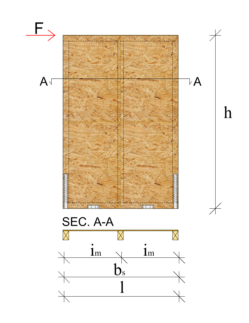
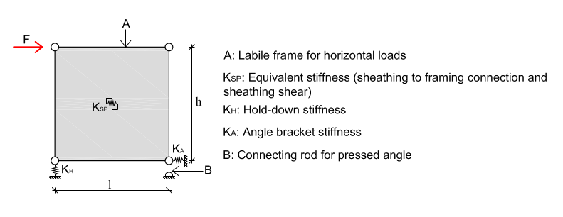
The elastic horizontal displacement of a light timber frame wall subjected to an horizontal force can be obtained by adding the following contributions of deformation.
Displacement due to the connections between the sheathing and the frame
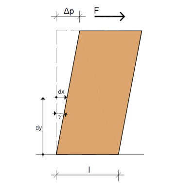
Displacement due to the sheathing panels
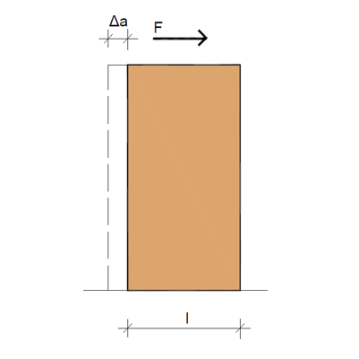
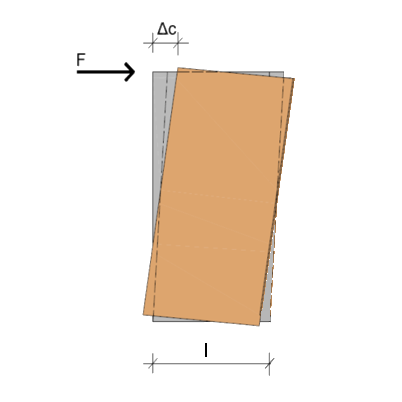
Displacement due to the rigid body translation
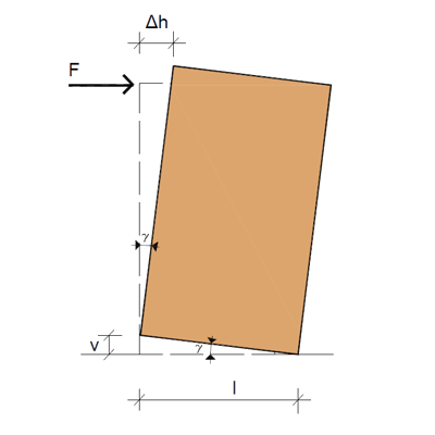
Displacement due to the rigid body rotation
MODELLING WITH A FINITE ELEMENT SOFTWARE
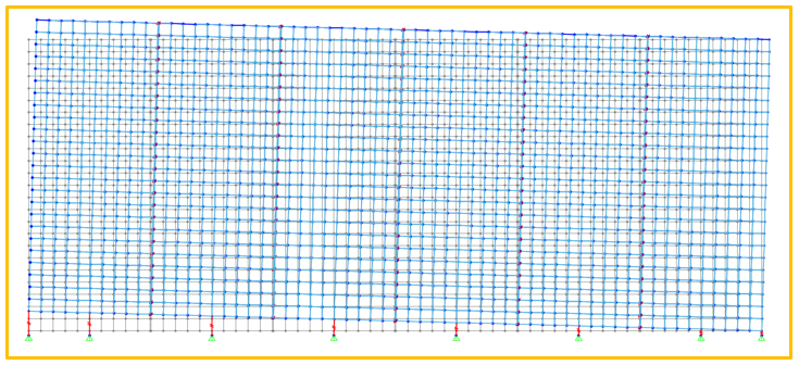
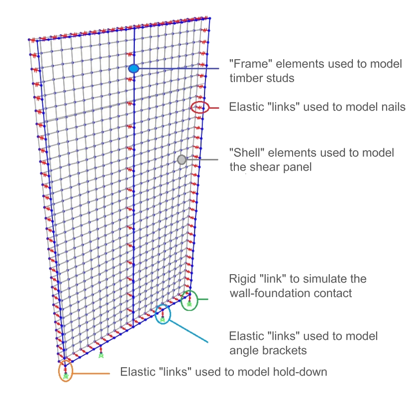
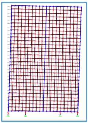
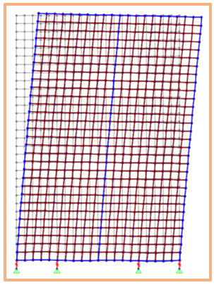
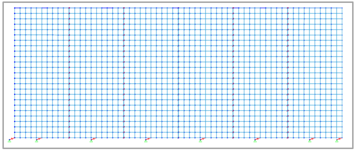
Modelling timber light-frame walls through finite element software is very onerous and complicated. As shown in the following figure, to evaluate correctly the horizontal stiffness of the wall, you need to use:
- “frame” elements to model the frame elements;
- “shell” elements to model the sheathing panel;
- “link” elements to model the connections between the sheating and the frame. Every nail is modeled with a link with the real stiffness of the fastener;
- “link” elements to simulate the hold down and the angle brackets.
MODELLING WITH TIMBERTECH BUILDINGS
Modelling with TimberTech Building is very simple and fast. The user has to define the geometrical and mechanical properties for each wall tipology.
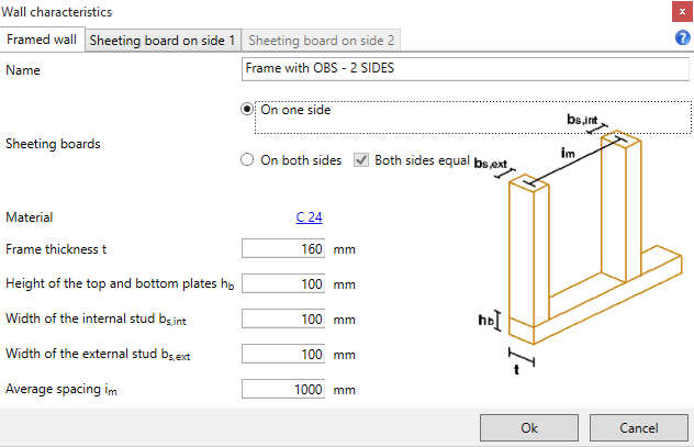
Frame properties
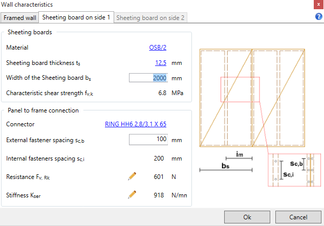
Sheating board properties
CASE STUDY
In this case study there is a comparison between the software TimberTech Buildings and a finite element software for a wall with a length of 2 m and an height of 3 m. The wall presents the following characteristics:
- the frame has a thickness of 160 mm, the width of the studs is equal to 100 mm and the spacing between studs is 1000 mm;
- the sheathing panel is an OSB/2 with a thickness of 12,5 mm. The nails stiffness is 918 N/mm. The external fasteners spacing is 100 mm and the internal fasteners spacing is 200 mm;
- the wall is restrained to the foundation with an hold-down with a stiffness of 19977 kN/m and with two angle brackets with a stiffness of 52186 kN/m.
Results
Comparison between the results obtained with Timbertech Buildings and the results obtained with a finite element software
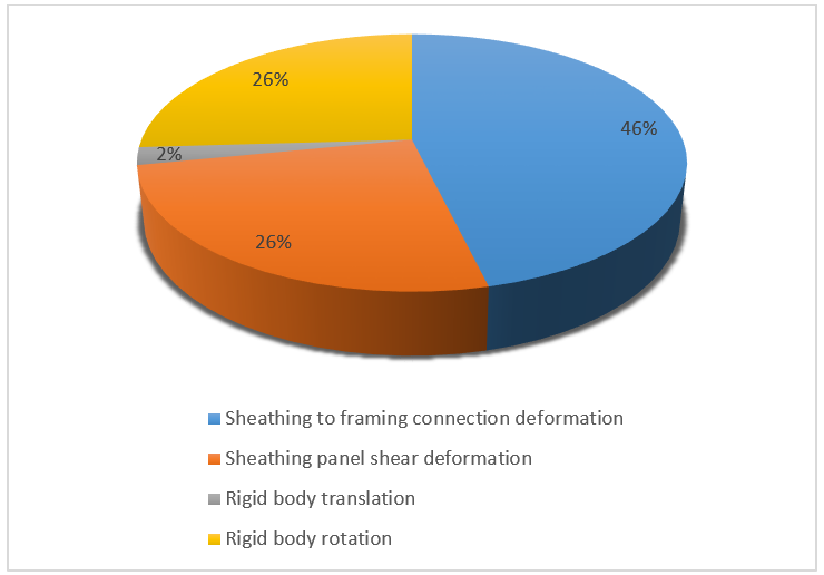
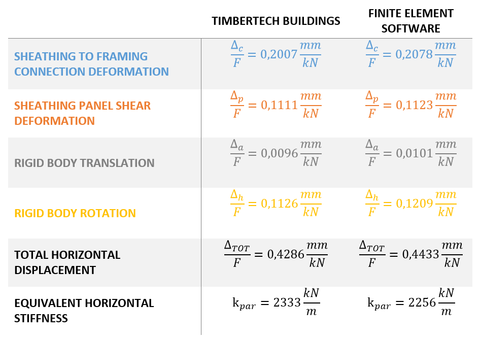
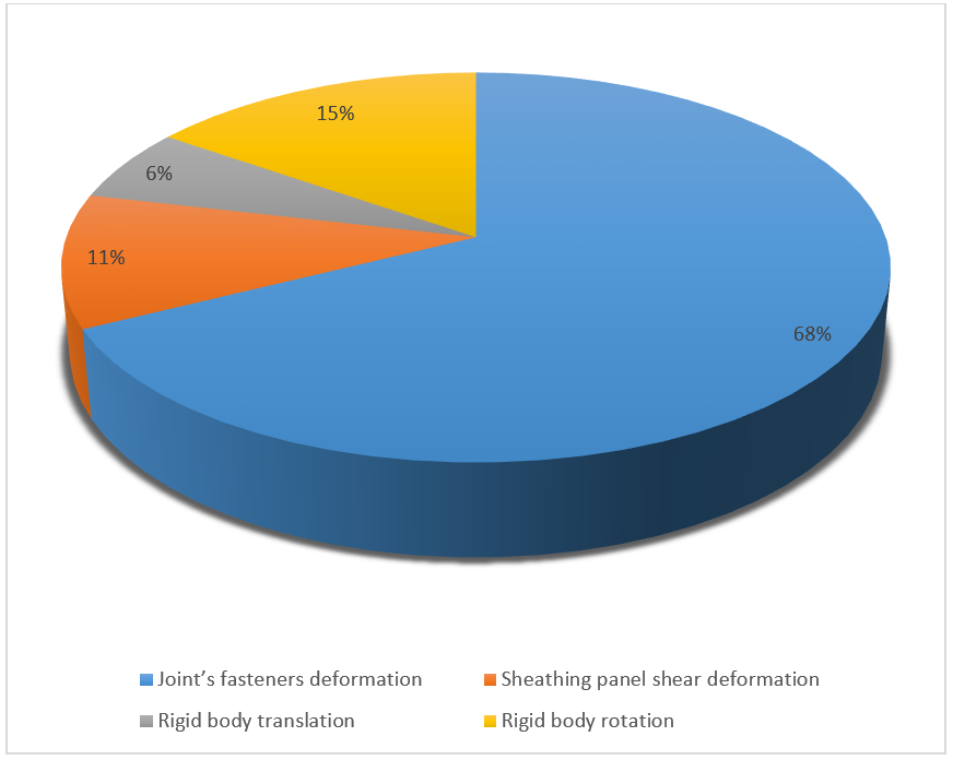
Deformation contributions
Deformation contributions obtained with TimberTech Buildings
From the table above, we can see how the results of the analytical model implemented in TimbertechBuildings are very similar to the results obtained with a finite element software. We achieved a wall stiffness that is very close to those obtained with a finite element software in spite of a more simple modelling of the wall.
In the table above, it is shown that the contribution of deformation given by the rigid body translation is negligible. On the other hand, the fasteners deformations and the rigid body rocking (hold-down connection) are very important.
Sheathing to framing connection deformation
Sheathing panel shear deformation
Rigid body translation
Rigid body rotation
Modelling of a CLT wall
CASE STUDY
INTRODUCTION
This section shows a comparison between a modelling of a CLT wall with a finite element software and a modelling with the software TimberTech Buildings. The aim of this comparison is to calculate and compare the several stiffness contributions given by the elements forming the wall.
The elastic horizontal displacement of a jointed CLT wall subjected to a horizontal force can be obtained by adding the following contributions of deformation:
- joints deformation;
- panel shear deformation;
- rigid body translation (angle brackets);
- rigid body rotation (hold-down).
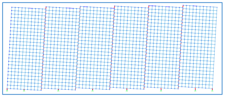
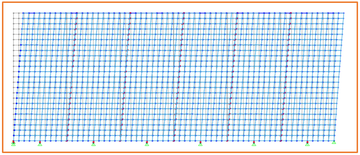
MODELLING WITH A FINITE ELEMENT SOFTWARE
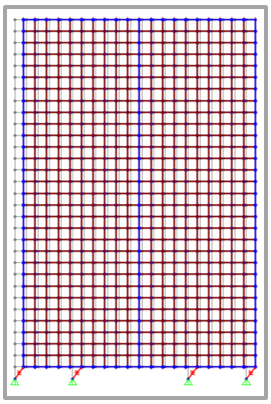
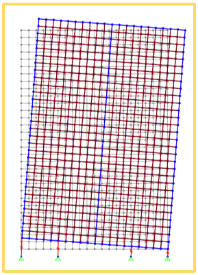
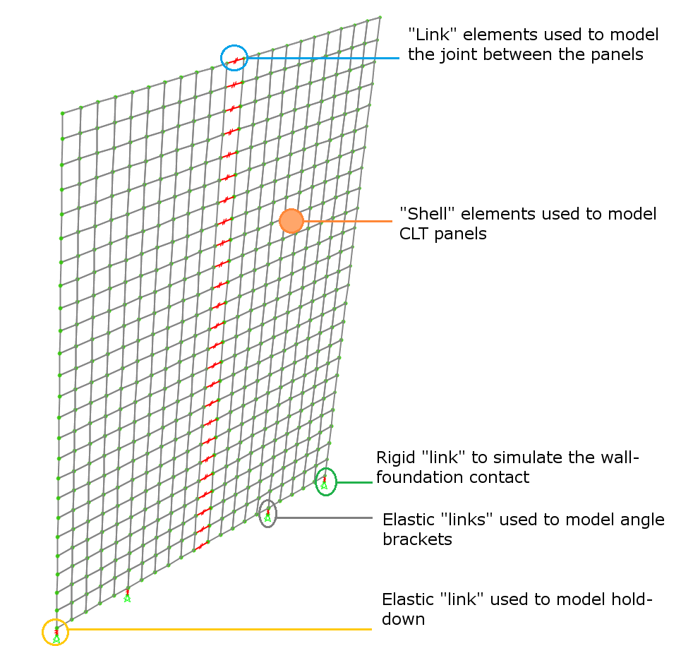
As shown in the following figure, to evaluate correctly the horizontal stiffness of the wall, you need to use:
- “shell” elements to model the CLT panels;
- “link” elements to model the joints between the CLT panels;
- “link” elements to simulate the hold down and the angle brackets.
MODELLING WITH TIMBERTECH BUILDINGS
Modelling a jointed CLT wall with TimberTech Building is very simple and fast. The user has to define the geometrical and mechanical properties for each wall tipology.
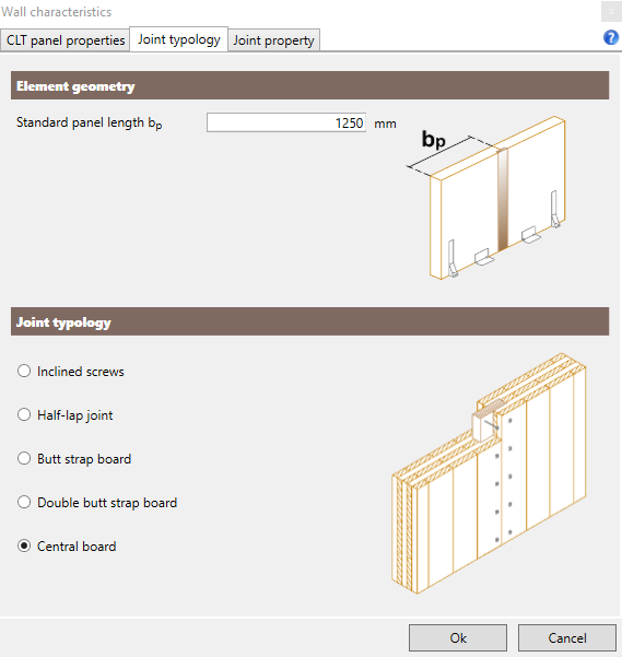
CLT wall properties in Timbertech Buildings
Joint tipology
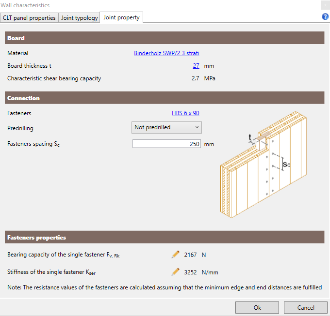
CLT wall properties in Timbertech Buildings
Joint properties
CASE STUDY
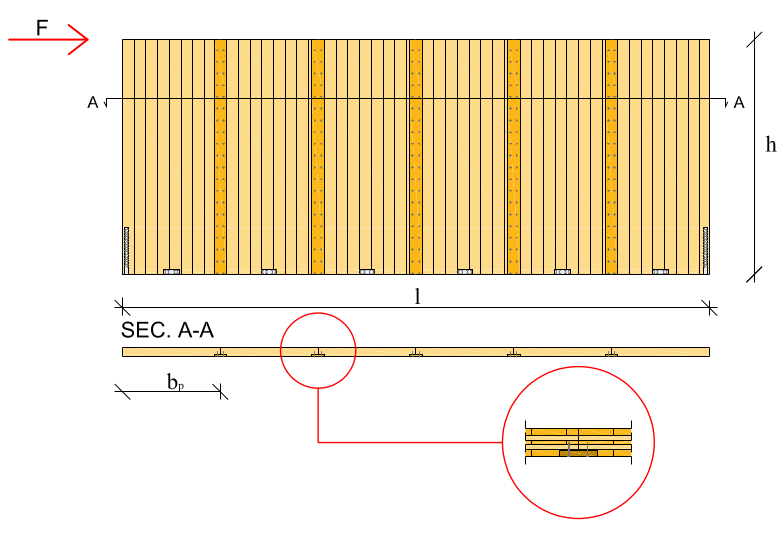
In this case study there is a comparison between the software TimberTech Buildings and a finite element software for a jointed CLT wall with a length of 7,5 m and an height of 3 m. The CLT wall has the following characteristics:
- the panels have a thickness of 120 mm (30 V – 20 H – 20 V – 20 H – 30 V) and a length of 1250 mm;
- the panels are jointed with a butt strap board. The fasteners have a spacing of 125 mm and a stiffness of 1881 kN/m;
- the wall is restrained to the foundation with an hold-down with a stiffness of 19977 kN/m and with two angle brackets with a stiffness of 52186 kN/m.
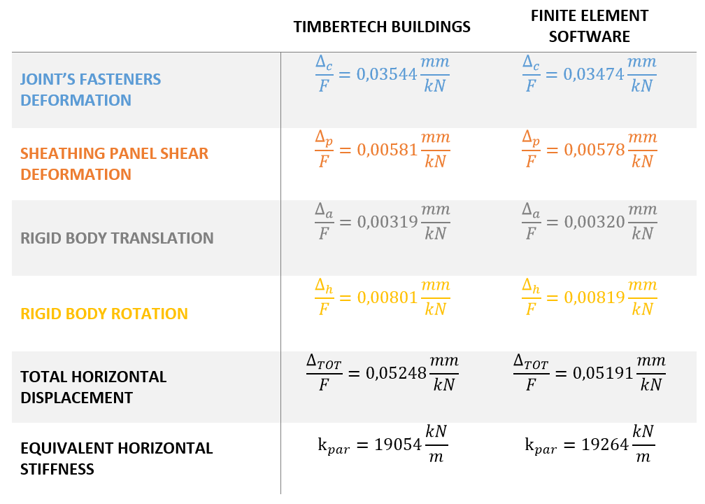
Table of results
Contributions of deformation in Timbertech Buildings
From the table above, we can see how the results of the analytical model implemented in TimbertechBuildings are very similar to the results obtained with a finite element software. We achieved a wall stiffness that is very nearly to the each one obtained with a finite element software in spite of a more simple modelling of the wall.
Joint's fasteners deformation
Panel shear deformation
Rigid body translation