Tutorials
Creation of a new project and description of the main window of the software – 2’57”
This video tutorial presents the procedure for the creation of a new project by defining the reference standard and the geo-location (for Italian standard only). It also illustrates the layout of the main window of the software.
Geometrical input of the structural elements – 6’05”
This video tutorial illustrates the procedure for the geometrical input of the structural elements (also starting from the import of a drawing in .dxf format) and presents an example of the geometrical modelling of a simple building.
Model view – 1’28”
This video tutorial illustrates the available options for the visualization of the model: views, extruded view, colour by property.
Materials archives – 3’24”
This video tutorial illustrates the databases of the structural elements available in the software.
Wall definition – 3’48”
This video tutorial illustrates the procedure for the definition of CLT and framed wall elements.
Floor and cross-section definition – 1’24”
This video tutorial illustrates the procedure for the definition of floor elements (joist floor, solid wood floor, CLT floor) and of the cross-section of linear elements (beams and columns made of timber and steel).
Definition of the connections at the base of wall elements – 2’55’
This video tutorial illustrates the procedure for the definition of the connections at the base of wall elements starting from the software databases.
Management of the Project properties tab – 2’31”
This video tutorial illustrates the Project properties tab and presents all the available design options.
Model validation – 1’53”
This video tutorial illustrates the procedure for the validation of the model before proceeding with the analysis.
Analysis results – 7’37’
This video tutorial presents the available analysis options and illustrates how to manage the results in terms of actions and checks.
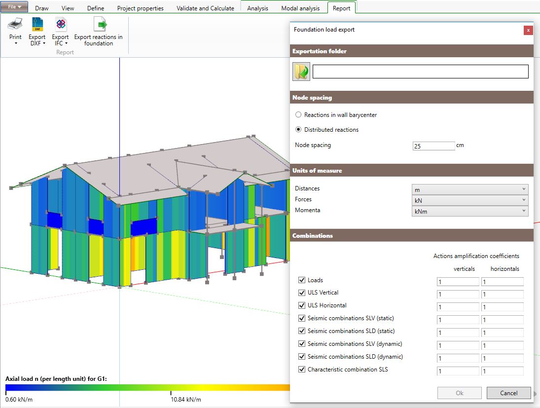
Export of design documents – 3’01”
This video tutorial presents the available documents that the software is able to export: calculation report, drawings, model in .ifc format, actions at the base of the structure.
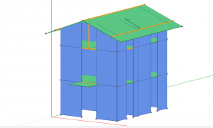
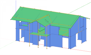
Geometrical definition of pitched roofs – 6’49”
This tutorial illustrates how to geometrically define a pitched roof in TimberTech Buildings.
Examples
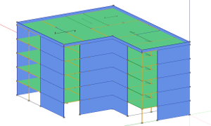
Example of a platform-frame building
Example of a CLT (Cross Laminated Timber) building
Example of export of reactions in foundation
5-storey building in CLT of the publication “The seismic behaviour of buildings erected in Solid Timber Construction, G.Schickhofer, A. Ringhofer” modeled in TimberTech Buildings