This work illustrates the procedure for the capacity design of a light timber frame building in ductility class DCM. It also presents a practical application to a case study: a two-storey structure is designed using the software TimberTech Buildings, of which the calculation report is totally reproduced.
Dissipative structural behaviour
Earthquake-resistant timber buildings should be designed considering either:
- dissipative structural behaviour;
- low-dissipative structural behaviour.
In the first concept the capability of parts of the structure (dissipative zones) to resist earthquake actions out of their elastic range is taken into account. Dissipative zones shall be located in joints and connections, whereas the timber members themselves shall be regarded as behaving elastically.
In the second concept the action effects are calculated on the basis of an elastic global analysis without taking into account non-linear material behaviour.
Ductility classes and overstrength factor
Depending on their ductile behaviour and energy dissipation capacity under seismic actions, buildings shall be assigned to one of the three following ductility classes:
- DCH, high capacity to dissipate energy;
- DCM, medium capacity to dissipate energy;
- DCL, low capacity to dissipate energy.
In DCH and DCM the European standard (UNI EN 1998-1 §8.1.3) requires the use of the capacity design procedure.
The capacity design has the purpose of ensuring a ductile behaviour to the dissipative structure and operates as follows:
- distinguishes elements and mechanisms, both local and global, into ductile and fragile;
- aims to avoid local brittle ruptures and the activation of global brittle or unstable mechanisms;
- aims at locating the energy dissipations by hysteresis in areas of the ductile elements identified and designed for this purpose.
To ensure the correct behaviour of the structure, the seismic resistance of the local/global brittle elements/mechanisms must be designed to be grater than that of the ductile elements/mechanisms. To ensure compliance with this inequality, both locally and globally, the strength of the ductile elements/mechanisms is increased by means of a suitable coefficient γRd known as the “overstrength factor”; starting from this increased capacity, the capacity of the brittle elements/mechanisms is sized. This coefficient is defined as equal to 1.3 for the ductility class DCM and 1.6 for the ductility class DCH.
The resistance demand evaluated with the capacity design criteria can be assumed not to exceed the strength demand evaluated for the non-dissipative structural behaviour.
Dissipative zones and non-dissipative zones
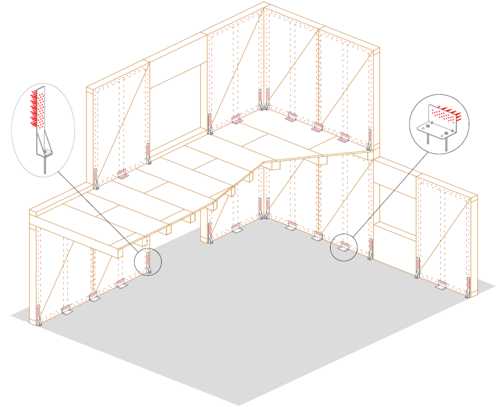
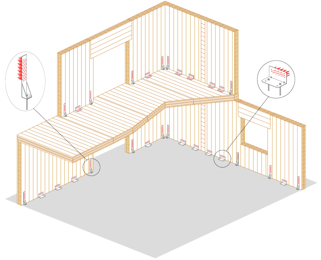
Considering a light timber frame building in ductility class DCM, the dissipative zones consist of:
- mechanical connection between frame and cladding sheets;
- ductile elements of the tension connection (for example the nailing);
- ductile elements of the shear connection (for example the nailing).
The non-dissipative zones are instead represented by:
- cladding sheets;
- brittle elements of the tension connection (for example the concrete anchors);
- brittle elements of the shear connection (for example the concrete anchors);
- timber elements.

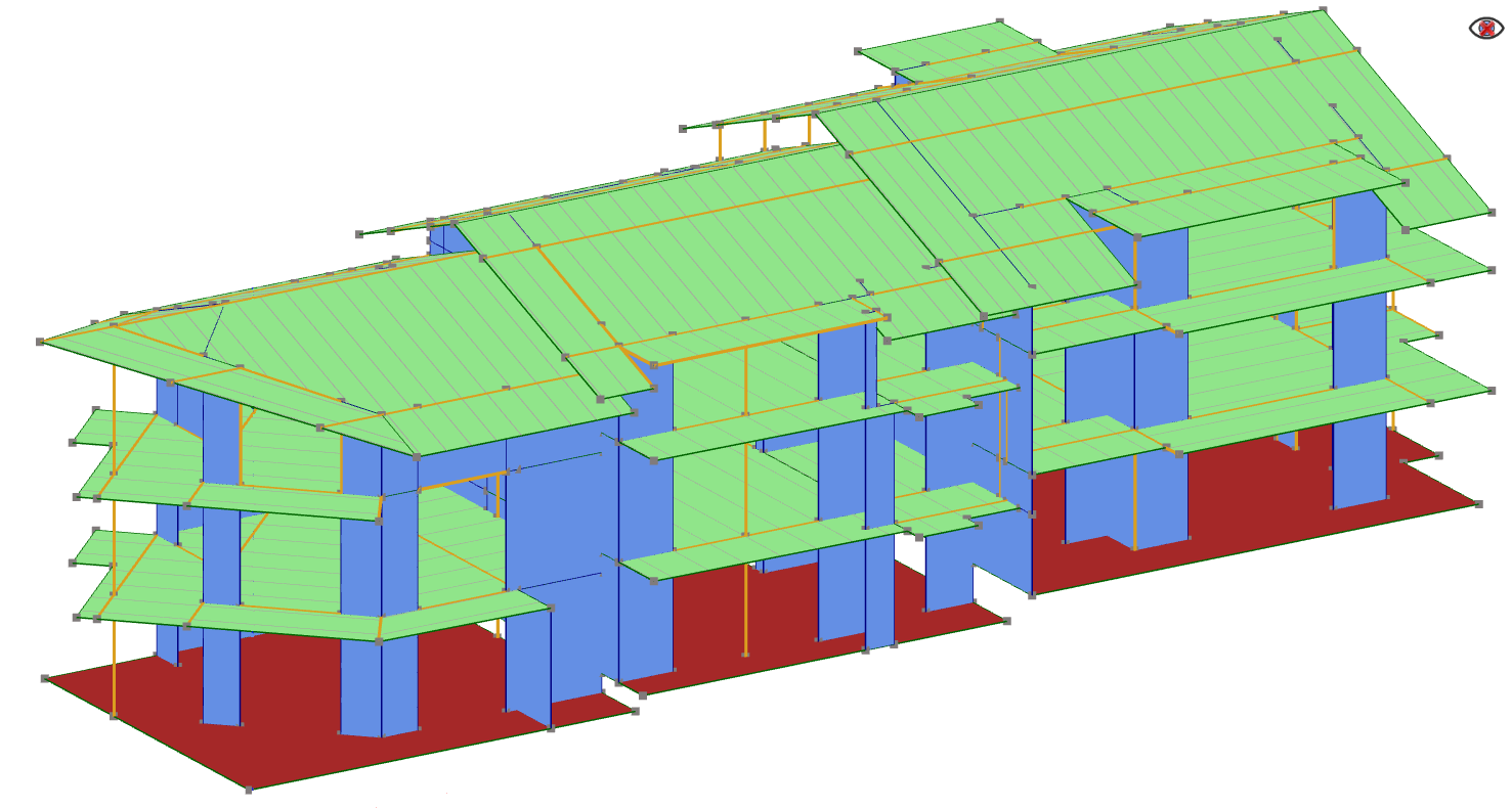
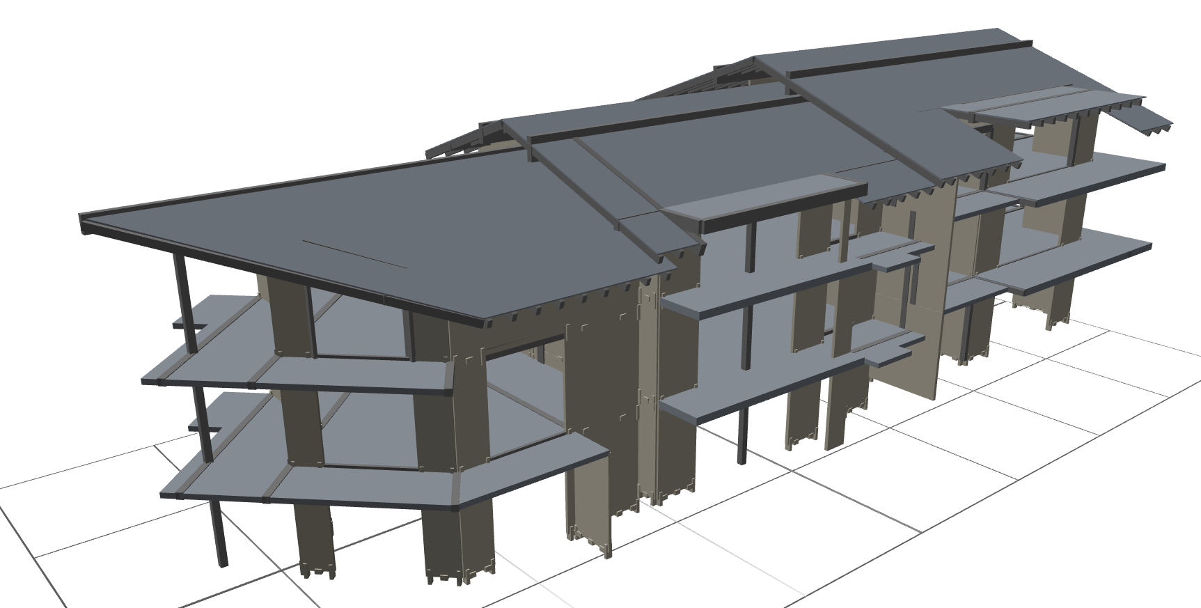
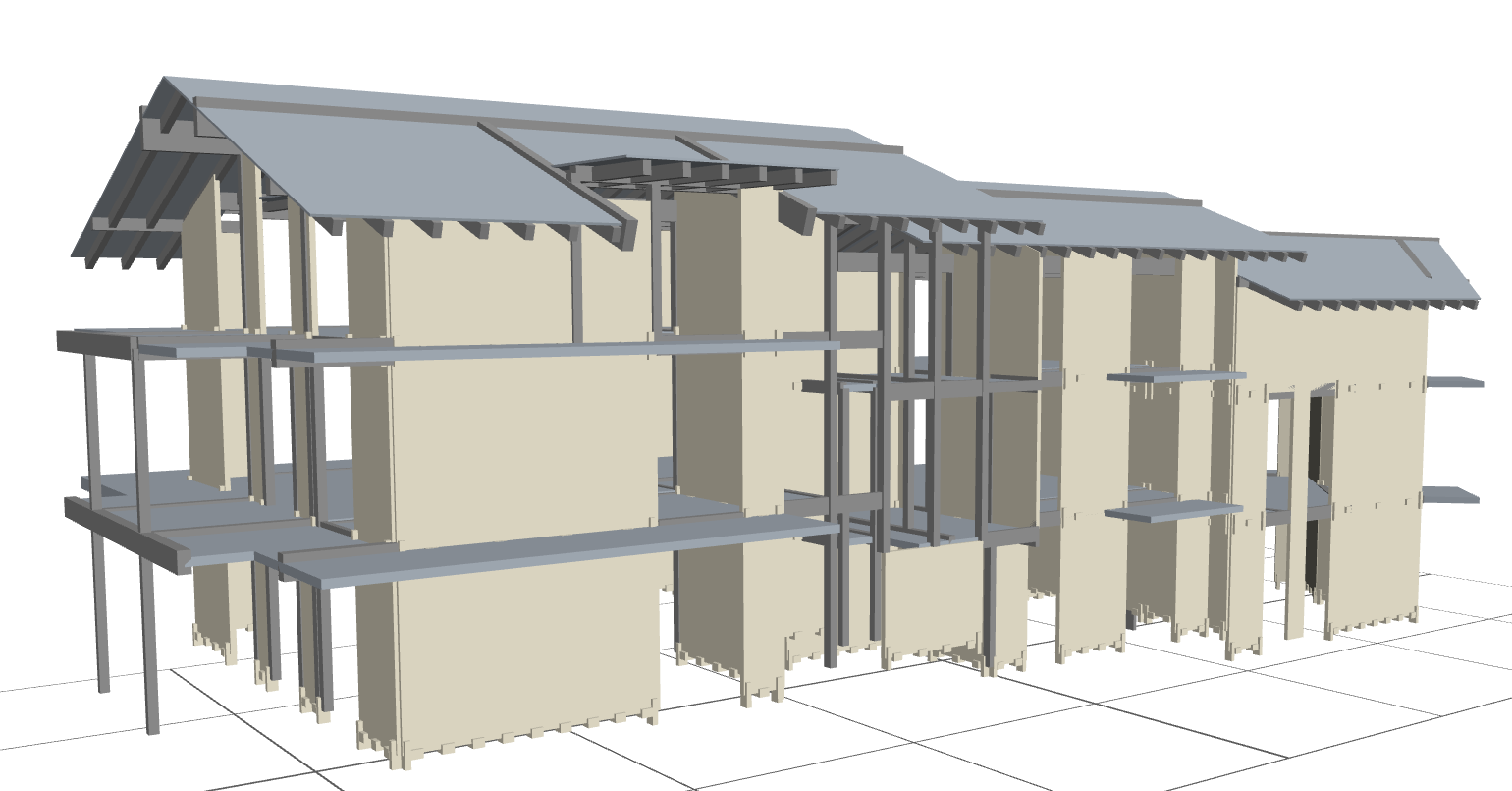
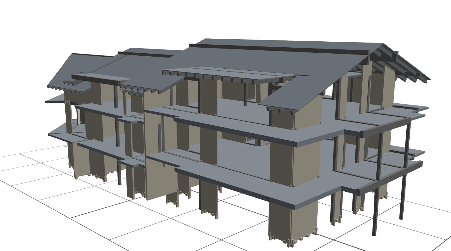
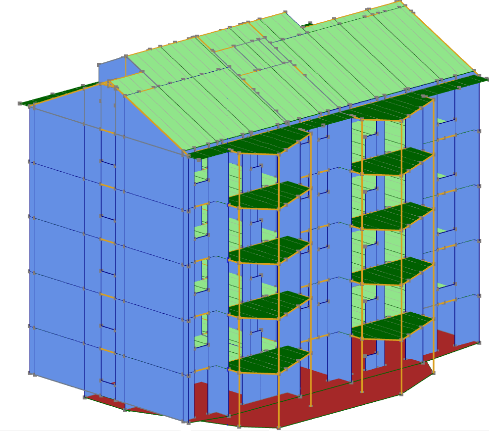
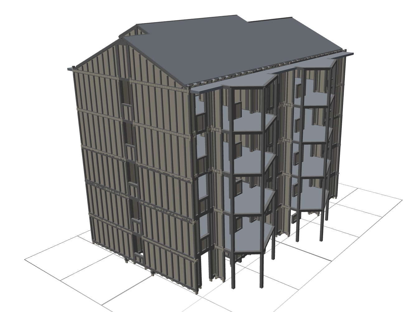
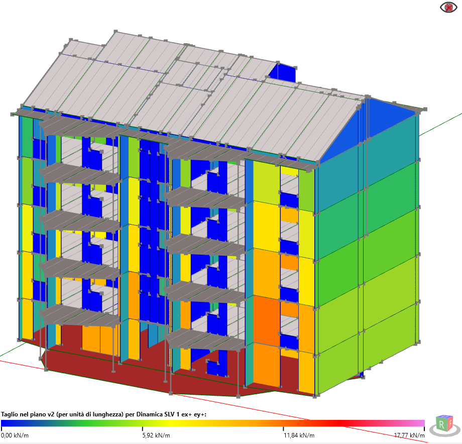
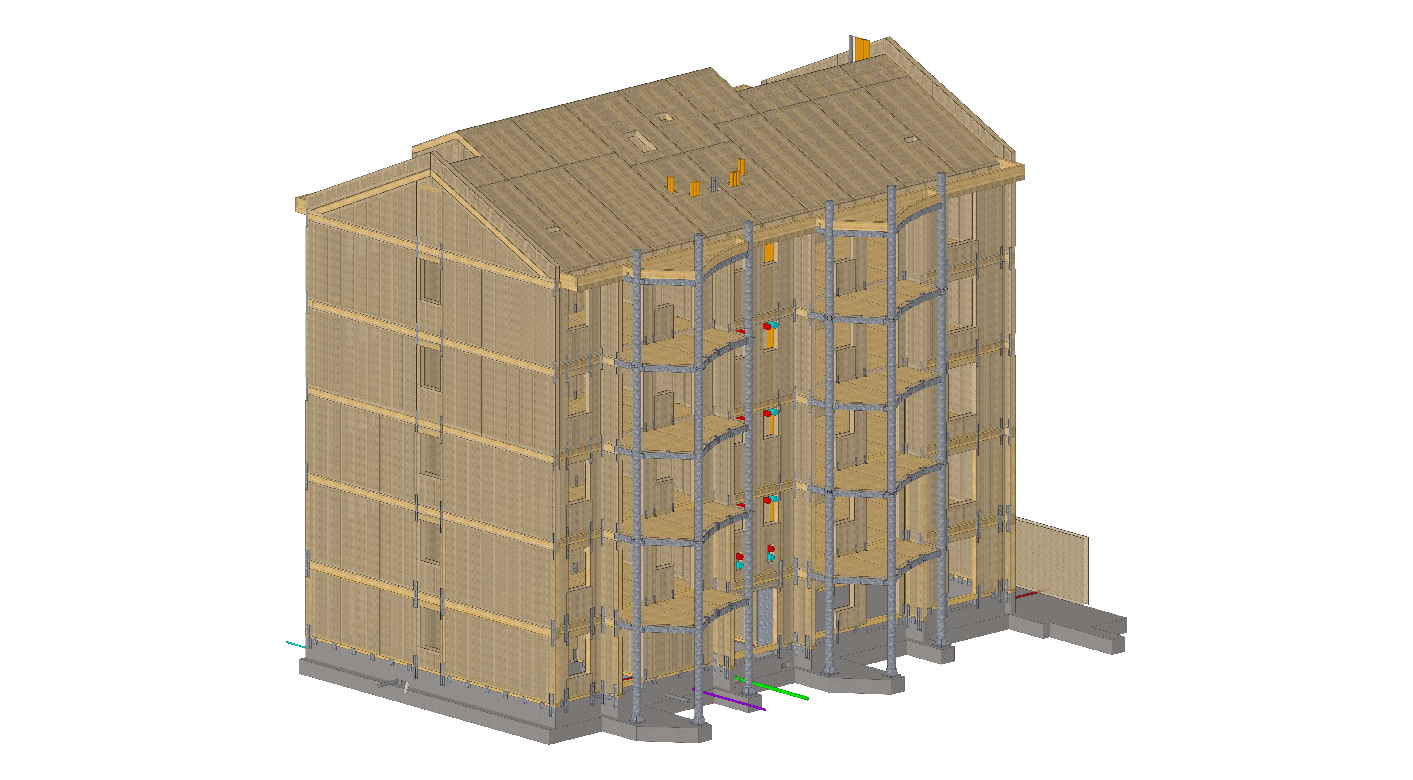
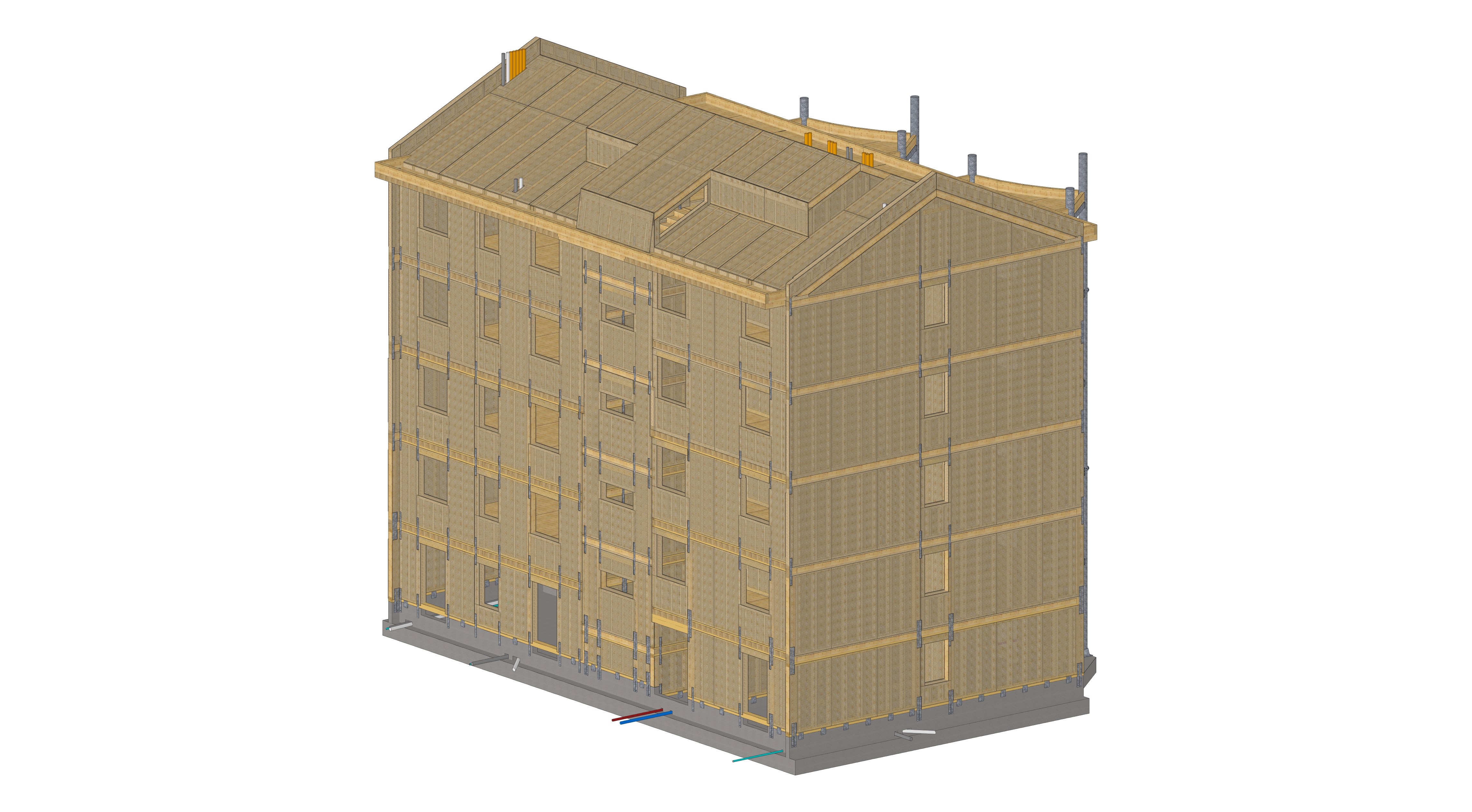
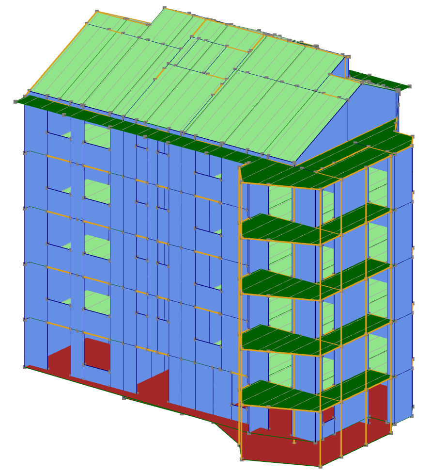
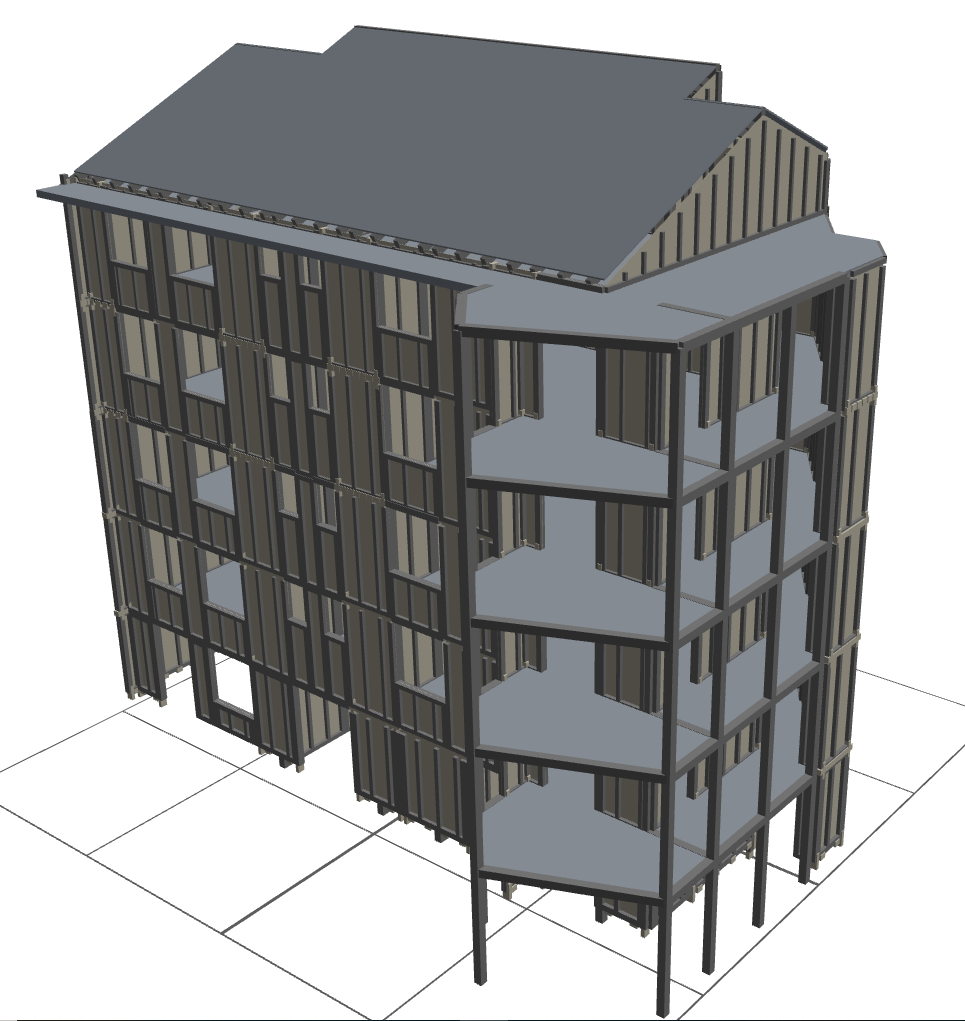
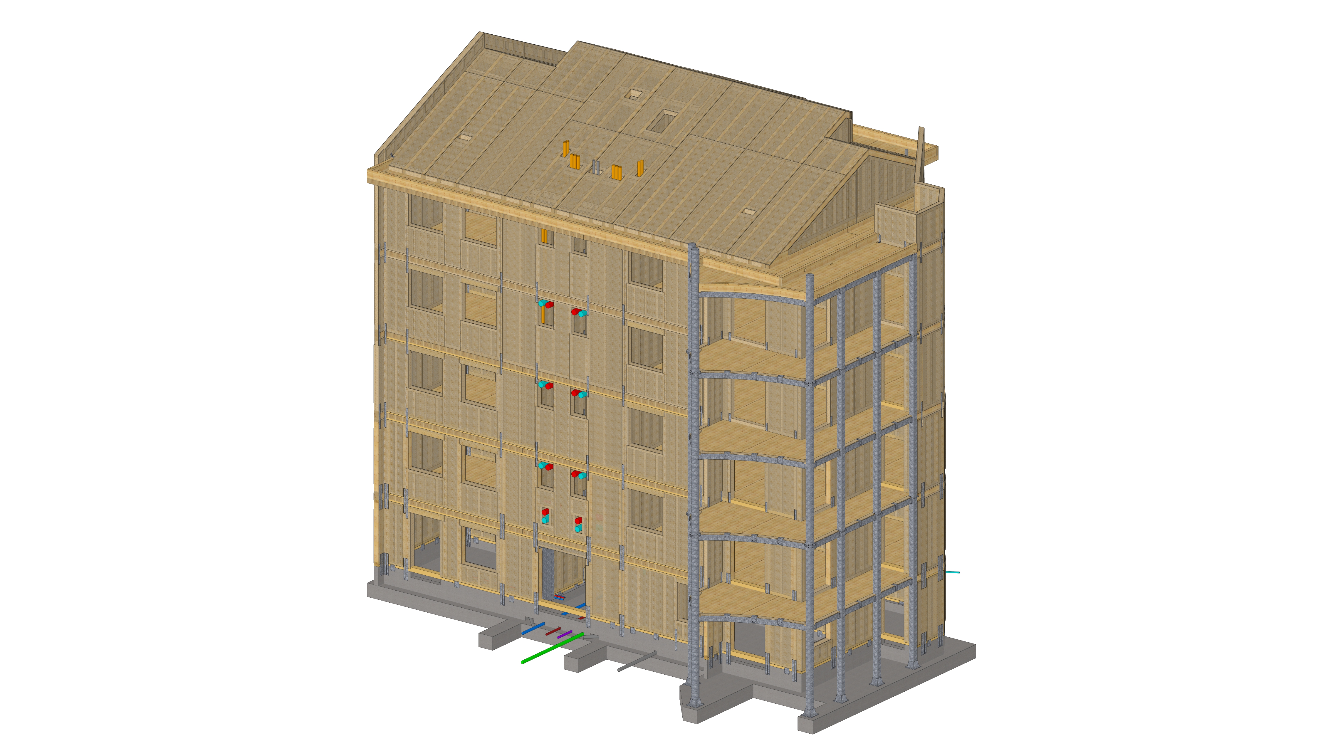
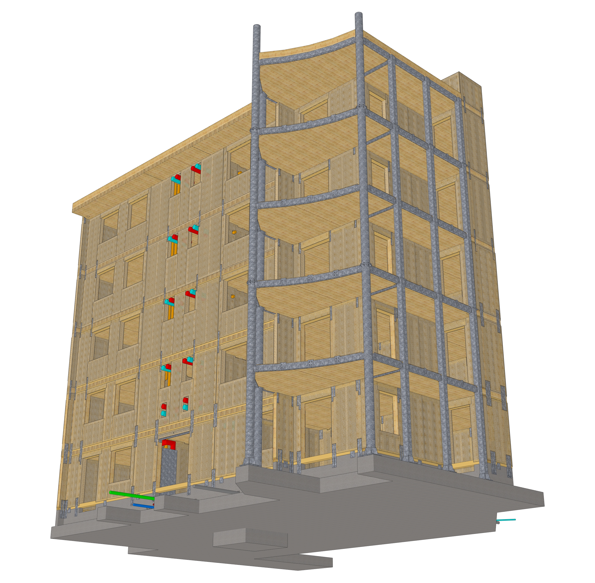
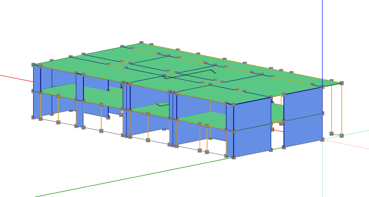
Figure 1 – Light timber frame building in ductility class DCM: dissipative zones
… continue reading in the PDF containing also the calculation report.
Download