Capacity design (Ductility class DCM) of a light timber frame building

This work illustrates the procedure for the capacity design of a light timber frame building in ductility class DCM. It also presents a practical application to a case study: a two-storey structure is designed using the software TimberTech Buildings, of which the calculation report is totally reproduced.

Dissipative structural behaviour

Earthquake-resistant timber buildings should be designed considering either:

  • dissipative structural behaviour;
  • low-dissipative structural behaviour.

In the first concept the capability of parts of the structure (dissipative zones) to resist earthquake actions out of their elastic range is taken into account. Dissipative zones shall be located in joints and connections, whereas the timber members themselves shall be regarded as behaving elastically.

In the second concept the action effects are calculated on the basis of an elastic global analysis without taking into account non-linear material behaviour.

Ductility classes and overstrength factor

Depending on their ductile behaviour and energy dissipation capacity under seismic actions, buildings shall be assigned to one of the three following ductility classes:

  • DCH, high capacity to dissipate energy;
  • DCM, medium capacity to dissipate energy;
  • DCL, low capacity to dissipate energy.

In DCH and DCM the European standard (UNI EN 1998-1 §8.1.3) requires the use of the capacity design procedure.

The capacity design has the purpose of ensuring a ductile behaviour to the dissipative structure and operates as follows:

  • distinguishes elements and mechanisms, both local and global, into ductile and fragile;
  • aims to avoid local brittle ruptures and the activation of global brittle or unstable mechanisms;
  • aims at locating the energy dissipations by hysteresis in areas of the ductile elements identified and designed for this purpose.

To ensure the correct behaviour of the structure, the seismic resistance of the local/global brittle elements/mechanisms must be designed to be grater than that of the ductile elements/mechanisms. To ensure compliance with this inequality, both locally and globally, the strength of the ductile elements/mechanisms is increased by means of a suitable coefficient γRd known as the “overstrength factor”; starting from this increased capacity, the capacity of the brittle elements/mechanisms is sized. This coefficient is defined as equal to 1.3 for the ductility class DCM and 1.6 for the ductility class DCH.

The resistance demand evaluated with the capacity design criteria can be assumed not to exceed the strength demand evaluated for the non-dissipative structural behaviour.

Dissipative zones and non-dissipative zones

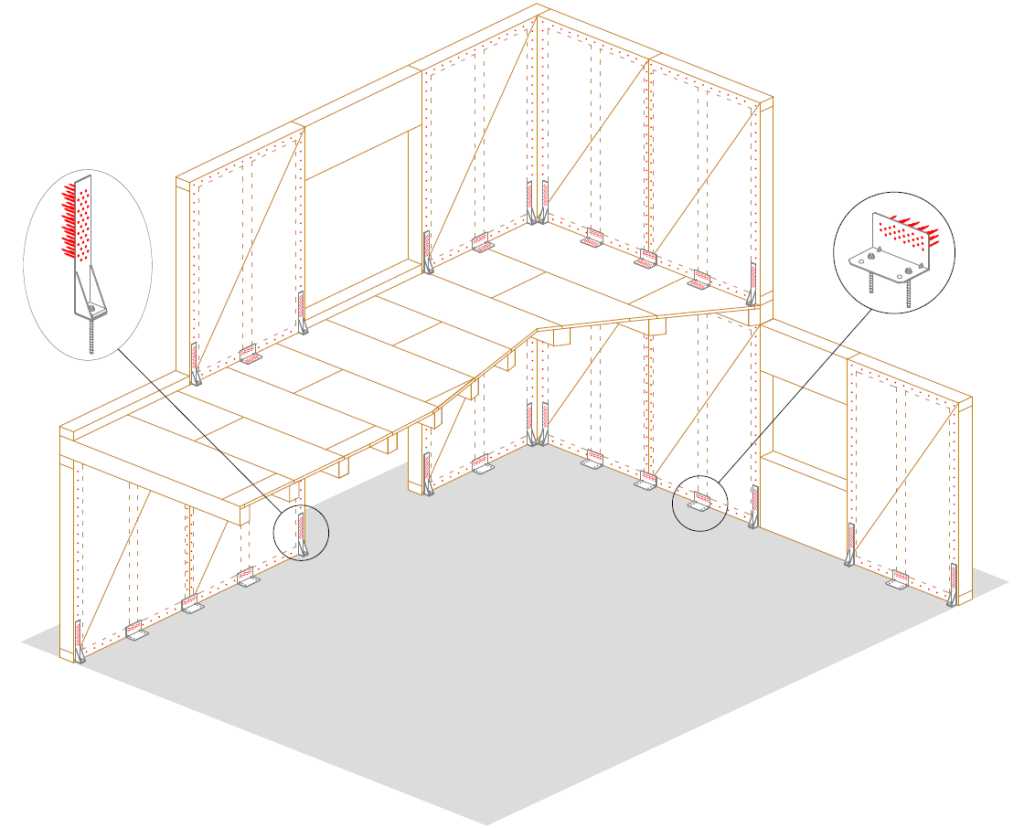
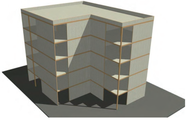
Considering a light timber frame building in ductility class DCM, the dissipative zones consist of:

  • mechanical connection between frame and cladding sheets;
  • ductile elements of the tension connection (for example the nailing);
  • ductile elements of the shear connection (for example the nailing).

The non-dissipative zones are instead represented by:

  • cladding sheets;
  • brittle elements of the tension connection (for example the concrete anchors);
  • brittle elements of the shear connection (for example the concrete anchors);
  • timber elements.

Progettazione in capacità edificio in legno

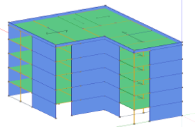
Figure 1Light timber frame building in ductility class DCM: dissipative zones

… continue reading in the PDF containing also the calculation report.

Download

Capacity design (Ductility class DCM) of a CLT building

This work illustrates the procedure for the capacity design of a CLT building. It also presents a practical application to a case study: a two-storey structure is designed using the software TimberTech Buildings, of which the calculation report is totally reproduced.

Dissipative structural behaviour

Earthquake-resistant timber buildings should be designed considering either:

  • dissipative structural behaviour;
  • low-dissipative structural behaviour.

In the first concept the capability of parts of the structure (dissipative zones) to resist earthquake actions out of their elastic range is taken into account. Dissipative zones shall be located in joints and connections, whereas the timber members themselves shall be regarded as behaving elastically.

In the second concept the action effects are calculated on the basis of an elastic global analysis without taking into account non-linear material behaviour.

Ductility classes and overstrength factor

Depending on their ductile behaviour and energy dissipation capacity under seismic actions, buildings shall be assigned to one of the three following ductility classes:

  • DCH, high capacity to dissipate energy;
  • DCM, medium capacity to dissipate energy;
  • DCL, low capacity to dissipate energy.

In DCH and DCM the European standard (UNI EN 1998-1 §8.1.3) requires the use of the capacity design procedure.

The capacity design has the purpose of ensuring a ductile behaviour to the dissipative structure and operates as follows:

  • distinguishes elements and mechanisms, both local and global, into ductile and fragile;
  • aims to avoid local brittle ruptures and the activation of global brittle or unstable mechanisms;
  • aims at locating the energy dissipations by hysteresis in areas of the ductile elements identified and designed for this purpose.

To ensure the correct behaviour of the structure, the seismic resistance of the local/global brittle elements/mechanisms must be designed to be grater than that of the ductile elements/mechanisms. To ensure compliance with this inequality, both locally and globally, the strength of the ductile elements/mechanisms is increased by means of a suitable coefficient γRd known as the “overstrength factor”; starting from this increased capacity, the capacity of the brittle elements/mechanisms is sized. This coefficient is defined as equal to 1.3 for the ductility class DCM and 1.6 for the ductility class DCH.

The resistance demand evaluated with the capacity design criteria can be assumed not to exceed the strength demand evaluated for the non-dissipative structural behaviour.

Dissipative zones and non-dissipative zones

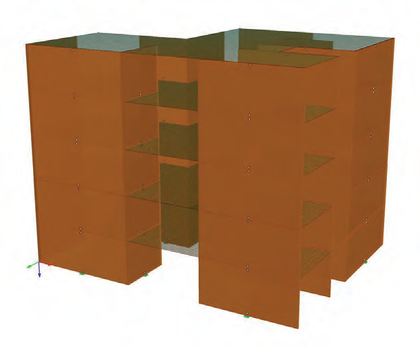
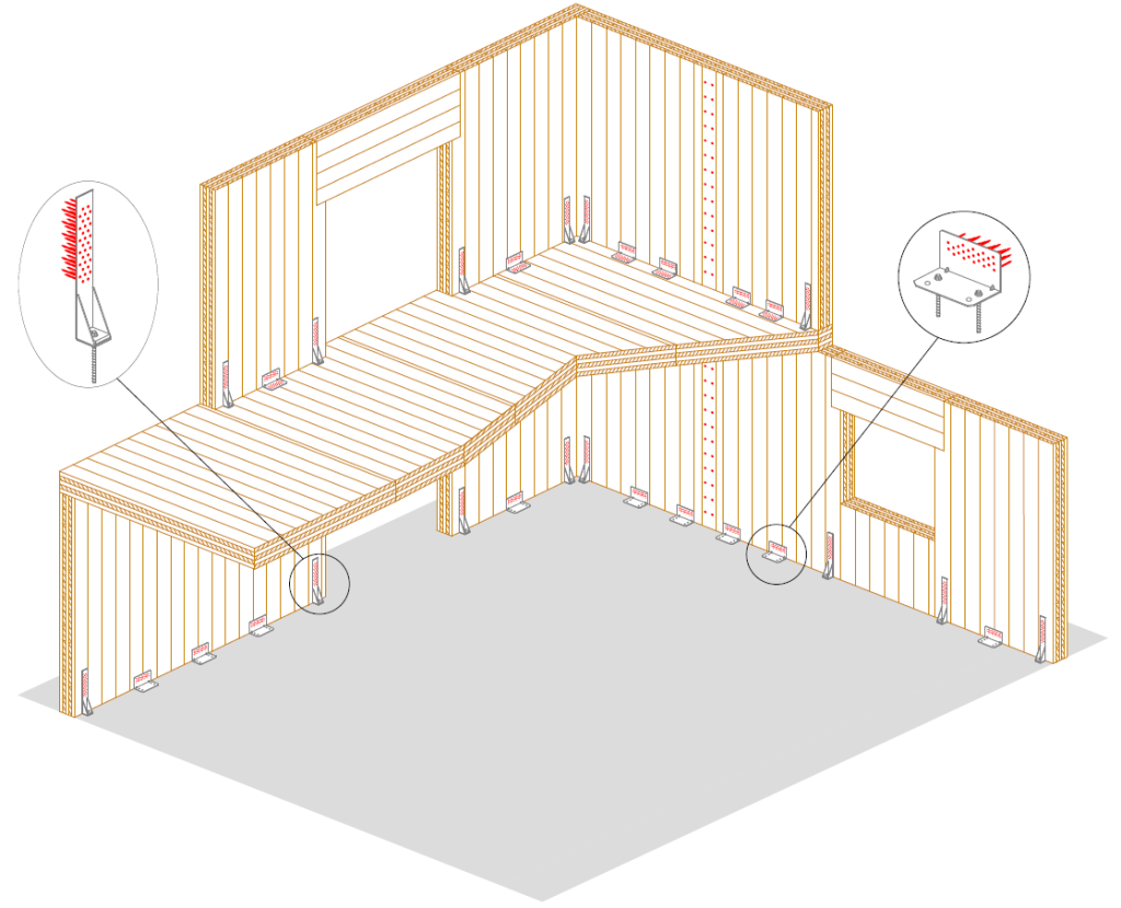
For a CLT building in ductility class DCM, the dissipative zones consist of:

  • mechanical connections between walls;
  • ductile elements of the tension connection (for example the nailing);
  • ductile elements of the shear connection (for example the nailing).

The non-dissipative zones are instead represented by:

  • brittle elements of the tension connection (for example the concrete anchors);
  • brittle elements of the shear connection (for example the concrete anchors);
  • timber elements.

Progettazione in capacità edificio in legno

Figure 1 – CLT building in ductility class DCM: dissipative zones

… continue reading in the PDF containing also the calculation report.
Download

Fire design of CLT elements. Glue line integrity maintained or not?

The check of CLT elements under fire conditions can be crucial in the design of a timber structure. Due to the layered structure of their cross-section, the calculation process is peculiar as pointed out in the examples below.

The charring depth of a CLT panel under fire conditions depends on the properties of the glue used in the panel assembly. The polyurethane glue (PUR), often used by manufacturers, is not resistant in case of high temperature meanwhile MUF glue (melamine-urea-formaldehyde) shows better performance.
This is why the new TimberTech Buildings additional module for the fire design of timber structures implements two calculation models to be applied according to the CLT properties certified by the manufacturer:

  • Glue line integrity maintained: the charring rate is assumed to be constant through the whole cross-section. This method can also be used when the manufacturer’s certificates suggest a constant charring rate (higher than that of the wood) to take into account the lower performance of the glue in a simplified manner.
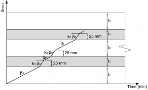
  • Glue line integrity not maintained: the charring rate is not constant and depends on the panel stratigraphy. The CLT cross-section can be seen as a sequence of layers where each one acts as a protective layer for the following one. Therefore, the method for protected elements provided by EN 1995-1-2 can be applied to obtain a charring rate trend such as the one reported in the figure below where the k3 factor usually has a value of 2.

CLT Charring Rate

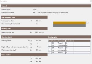
CLT design example: R60 with glue line integrity not maintained

CLT - Glue line integrity not maintained

  • Cross-section: 120 mm (20-30-20-30-20)
  • Glue: glue line integrity NOT maintained
  • Fire exposure: 60 minutes on one side
  • Unidimensional charring rate: beta0 = 0.65 mm/min
  • Charring depth: dchar,0 = 53 mm. Layer 1 (constant charring rate), layer 2 (double charring rate in the first 25 mm, then constant charring rate), strato 3 (double charring rate up to the required 60′)
  • Effective charring depth: def = dchar,0 + k0d0 = 60 mm
  • Effective cross-section: 60 mm (20-30-10)


Bending check 101% (MEd = 11.36 kNm)
Shear check 14% (VEd = 7.81 kNm)


Download the TimberTech Buildings calculation report about this example

Download


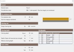
CLT design example: R60 with glue line integrity maintained

CLT - Glue line integrity maintained

  • Cross-section: 120 mm (20-30-20-30-20)
  • Glue: glue line integrity NOT maintained
  • Fire exposure: 60 minutes on one side
  • Unidimensional charring rate: beta0 = 0.65 mm/min
  • PCharring depth: dchar,0 = 39 mm. Constant charring rate through all layers
  • Effective charring depth: def = dchar,0 + k0d0 = 46 mm
  • Effective cross-section: 74 mm (20-30-20-4)


Bending check 55% (MEd = 11.36 kNm)
Shear check 12% (VEd = 7.81 kNm)


Download the TimberTech Buildings calculation report about this example

Download


Cross Laminated Timber (CLT) Beams Loaded in Plane: Testing Stiffness and Shear Strength

New paper by Francesco Boggian, Mauro Andreolli and Roberto Tomasi on the assessment of stiffness and shear strength of CLT beams loaded in-plane.

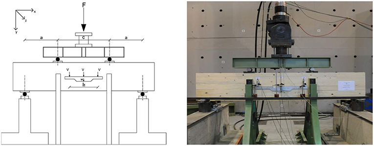
Set up

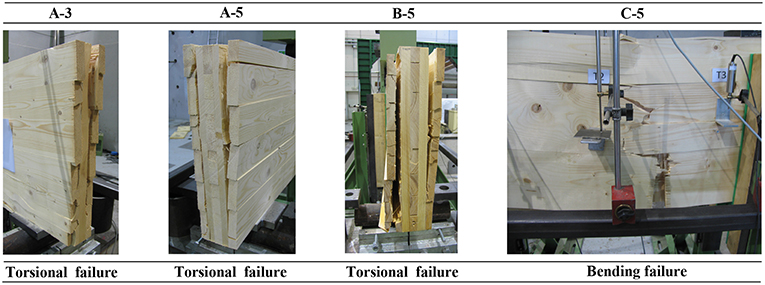
Abstract: Cross Laminated Timber (CLT) is a relatively new timber product used in construction that has gained popularity over the last decade. The product itself is constituted by multiple glued layers of juxtaposed boards, usually arranged in an orthogonal direction between one layer and the adjacent ones. This particular structure brings several benefits, such as the possibility to use the same product both for walls and slabs, since it can bear in-plane and out-of-plane loads. However, the mechanical behavior differs from usual timber products, and research is still ongoing to achieve common agreement on standard procedures for testing products and theories for evaluating stresses for safety verifications. This paper focuses on the in-plane shear behavior of CLT and analyzes the existing methods to evaluate shear stresses. An experimental part then presents a four-point bending test of CLT beams with a specific geometry to induce shear failure. Results are reported both for the elastic range test, measuring the Modulus of Elasticity, and for the failure test to investigate shear behavior with regard to different mechanisms. Previously exposed methods are used for the calculation of shear stresses and to analyze the correspondence between them, and the results are then compared with other existing tests and values in literature. A new test setup for future research is eventually proposed.

Failure modes

Continue…

Download the full paper

TimberTech Buildings: sold in 14 states

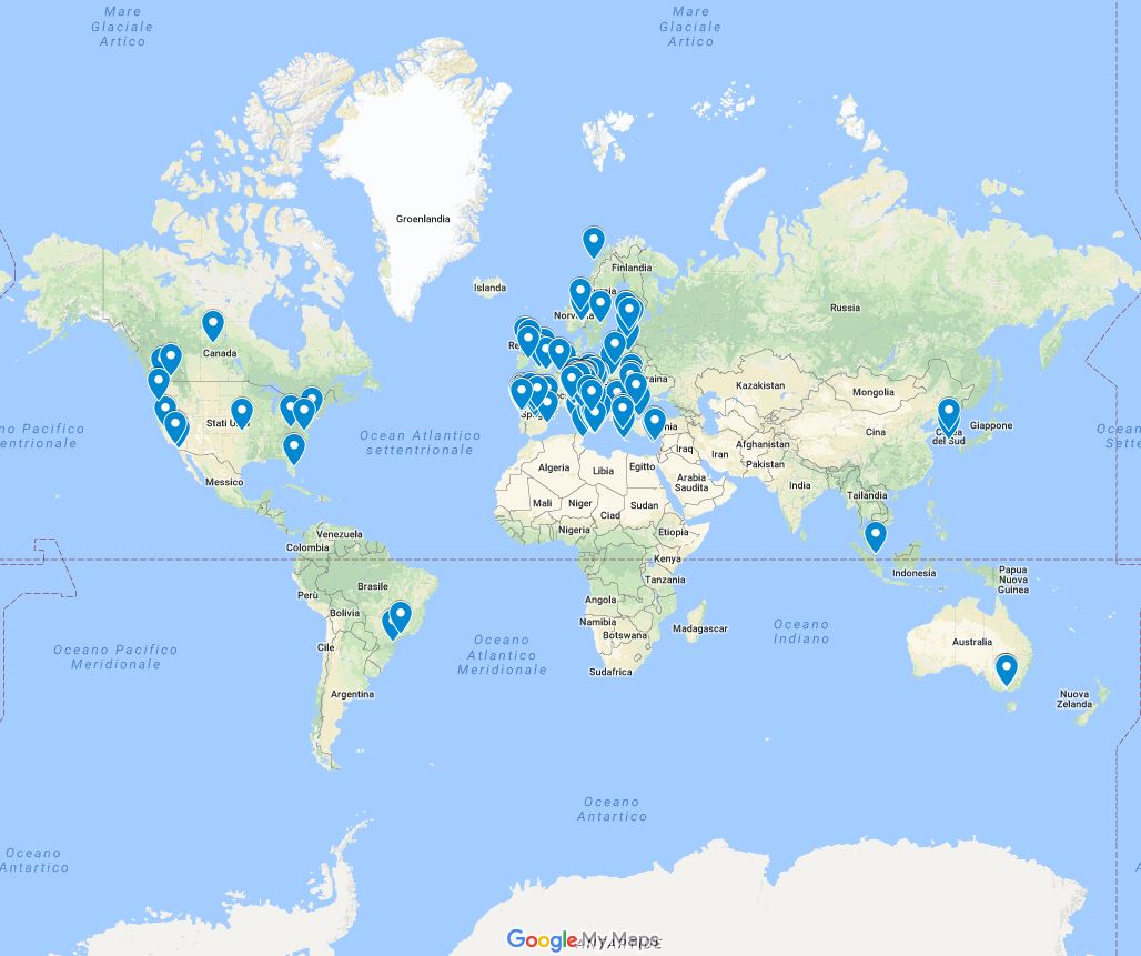
After long and hard work we are proud to share our important result regarding the software TimberTech Buildings. Thanks also to the translation in four languages (Italian, English, Spanish and Greek) we were able to sell it and distribute it in more than 14 countries worldwide.
In the map below you can view the places where some of the licenses have been activated (purchased by professionals and companies and educational versions given in use to students and professors).

Our resellers abroad.

The seismic behaviour of buildings erected in Solid Timber Construction


The report produced by the Institute of Timber Engineering and Wood Technology of Graz University of Technology “The seismic behaviour of buildings erected in Solid Timber Construction, G. Schickhofer, A. Ringhofer” is now available for download. It refers to the seismic design according to EN 1998 for a 5-storey reference building in CLT. In the section Tutorials & Samples you can download the sample file of the structure modeled with our software TimberTech Buildings.

CLT Training Course – COST Action FP 1004

The University of Trento has hosted from 15 to 17 April the Training Course “Structural design of Cross Laminated Timber (CLT)”. 80 among professors, researchers and technicians in the field of timber structures from 23 countries, were able to exchange views for 3 days on the design and calculation of CLT elements. A course to be repeated!

Software Rothoeng

Register on the site www.rothoblaas.com to download for free the software Rothoeng 2.0 beveloped by Timber Tech for Rotho Blaas!

Calculation software for the design and check of connections between main beam and other beams with fully threaded VGS and VGZ screws.

  • Design by ETA – 11/0030
  • Standards: EN 1995-1-1:2008 e NTC 2008 (Italy)
  • Export of technical design calculation report with customization options
  • Available in 7 languages